Rotate Points Around an Arbitrary Axis
(Horizontal Axis Method)
Steven Dutch, Professor Emeritus, Natural and Applied Sciences, University of Wisconsin - Green Bay
Rotations around an arbitrary axis are about the most complex stereonet constructions. They arise particularly when data from folded or tilted rocks must be restored to their original orientations when the rocks were horizontal. Current directions and magnetic pole orientations are examples. Multiple rotations also arise in universal-stage research in petrology.
The general sequence of steps necessary is as follows:
- Plot the data and the rotation axis.
- Rotate the rotation axis to a location where the data can be rotated on a stereonet. This means rotating the axis to either a vertical or horizontal orientation. In this example we will rotate the axis to a horizontal position. This example and the vertical-axis example use the same data.
- Rotate the data around the rotated axis.
- Rotate the rotated data and axis so that the rotated axis returns to its original orientation.
In other words everything has to be rotated at least twice, not counting rotations of the overlay. For very large data sets it may just pay to construct an oblique stereonet. (In my undergraduate structural geology class we were given a rotation problem involving 300 points! For something like that, you pretty much need to do each stage of the problem on a separate overlay.)
Example
Given a line trending 318 and plunging 37 degrees, rotate the line 70 degrees around an axis trending 025 and plunging 60 degrees.
 |
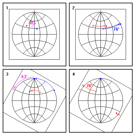
1. Plot the line (red) and the rotation axis (blue).
2. We need to get the axis to the primitive circle to rotate it to a horizontal position. Rotate the axis to the primitive circle and count off the rotation angle on the small circle. It turns out to be 76 degrees. Rotate the line by the same amount. The initial position of the line and axis are shown as open squares, the final positions as solid. 3. Rotate the overlay so the axis axis is at one pole. The required rotation in this case is 63 degrees. 4. Now rotate the line by 70 degrees around the rotation axis. Note that it exits the primitive circle. |
Situations like in Figure 4 are fairly common. The rotation takes the point beyond the primitive circle. The structural geology convention is shown here: the opposite end of the line rotates onto the opposite side of the net. If you want to avoid situations like this, there are several options:
- Possibly using the vertical-axis method might avoid it.
- Sometimes rotating the overlay to reposition the axis before step 2 can help. It introduces an extra step, but if you can see that you will have many points exiting the primitive circle, it might be worth it. Just remember that you did an extra rotation, and rotate the overlay back to its original position as your last step.
 |
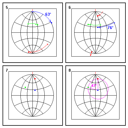
5. Now we undo the previous rotations. Rotate the axis back to where it was in step 3, and rotate the rotated line the same amount. The original position of the line is shown in green from here on.
6. Now rotate the axis back to its original orientation, reversing the rotation in step 2. Rotate the rotated line as well. Note that this rotation carries the line back out of the primitive circle. This rotation should return the original line to its starting point. 7. The final result. The rotated position trends 008 degrees and plunges 14 degrees. 8. As a check, the angle between the axis and both positions of the line should be the same (47 degrees in this case). |
The original and rotated positions of the line should both lie on a small circle centered on the rotation axis (shown in purple in figure 8). Note that this construction and the vertical-axis method give the same result, as they should.
Return to Course Syllabus
Return to Techniques Manual Index
Return to Professor Dutch's Home Page
Created 11 September 2000, Last Update 13 September 2000