Construct a Fold Cross-Section Using the Kink Method
Steven Dutch, Professor Emeritus, Natural and Applied Sciences, University of Wisconsin - Green Bay
How the Kink Method Works
It's fairly common for folds to exhibit uniform dips for a wide interval and then change dip abruptly. In other words the fold exhibits a series of kinks rather than smooth curvature. We can approximate such folds using the kink method. It is a bit more common these days for folds to be represented this way than with the Busk or arc method.
The basic method is to allow each dip measurement to define a zone where the dip is constant. The boundaries of the dip zones are the lines that bisect angles between adjacent dips. The example below begins with three different ways to find the bisector.
The actual point here the fold kinks may not coincide exactly with the bisector. Why should it? If you have two dips at points 1 and 2, the change in dip could come anywhere between them, and is not necessarily going to coincide with a line halfway between the two dips. This method, like all fold construction techniques, is an approximation.
Example
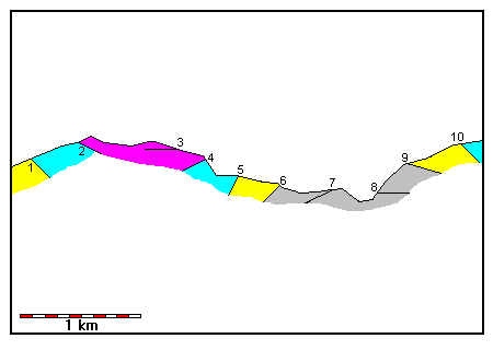 |
In the example at left, dip data are shown. We want to construct a cross-section that satisfies the data.
The stratigraphic units are colored here but will not be colored for most of the remaining diagrams. It is often better not to consider stratigraphy until after the cross-section is drawn. |
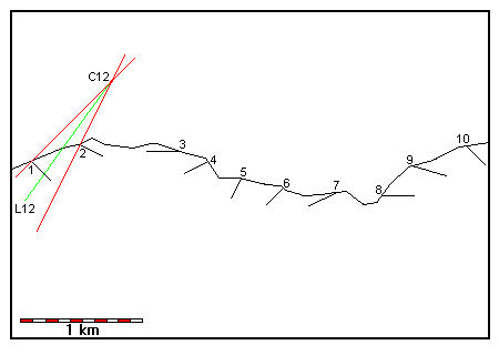 |
We first find the line L12 that bisects the angle between dips 1 and 2.
One way is to construct lines perpendicular to dips 1 and 2 (in red). They intersect at C12. Bisect the angle formed by the two perpendiculars (shown in green). |
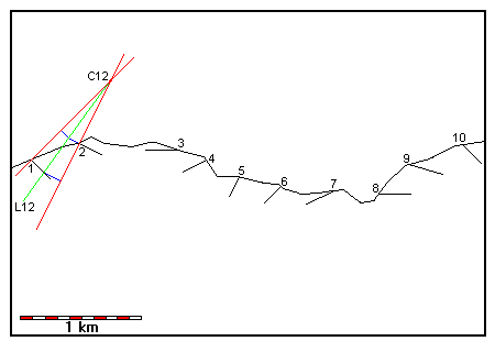 |
Extend the dips out to L12. When you cross the line, continue with the dip on the opposite side. That is, use dip angle 1 on the left side of line L12 and dip angle 2 on the right. |
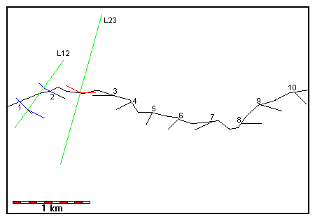 |
Here's another way: halfway between datum points 2 and 3, draw lines parallel to dips 2 and 3 (shown in red). Bisect the angle to find line L23 |
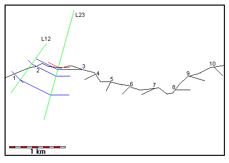 |
Extend dips 2 and 3 to L23, then continue on the opposite side of the line with the appropriate dip. For example, extend dip 2, then where it intersects L23, continue with dip 3.
We can also extend the line that originates at datum point 1. Between L12 and L23 it has dip 2, then on the right of L23 it has dip 3. |
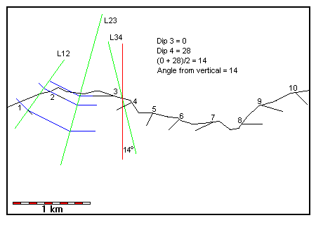 |
Yet another approach is to average two adjacent dips. The desired line passes through the midway point between the two datum points. Draw a vertical line through that point and measure the average angle from the vertical line. Pay careful attention to dip direction so that the line has the proper slope. |
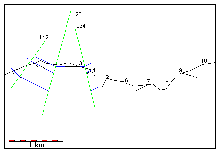 |
Lines left of L34 have dip 3, to the right they have dip 4. Continue the lines that originated at datum points 1 and 2 by extending them through L34 with the appropriate dips. |
Dips 5-10 are handled the same way, so the remaining illustrations simply show the results for each pair of dips.
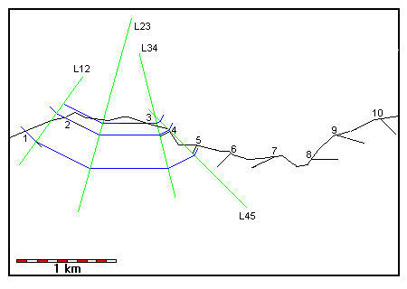 |
L45 constructed. Lines are extended to L34 and the dip beyond is indicated. Dips 4 and 5 are very close to already existing lines and are unlikely to give any new information, so we don't need to construct lines through dips 4 and 5 for now. |
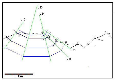 |
L56 constructed. The rocks at datum point 6 are stratigraphically lower than any we have so far seen, so we extend dip 6 to line L56, then continue to the left parallel to the previously drawn lines. |
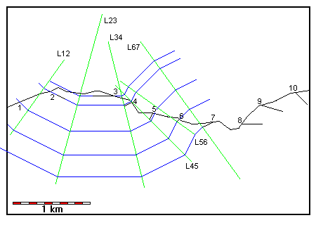 |
L67 constructed. The rocks at datum point 7 are even lower than those at datum point 6, so we also extend dip 7 to line L67, then continue to the left parallel to the previously drawn lines. |
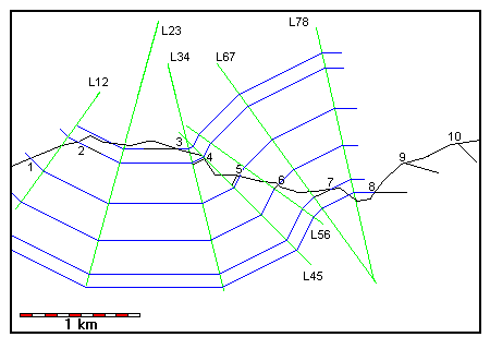 |
L78 constructed. The rocks at datum point 8 are still lower , so we also extend dip 8 to line L78, then continue to the left parallel to the previously drawn lines. |
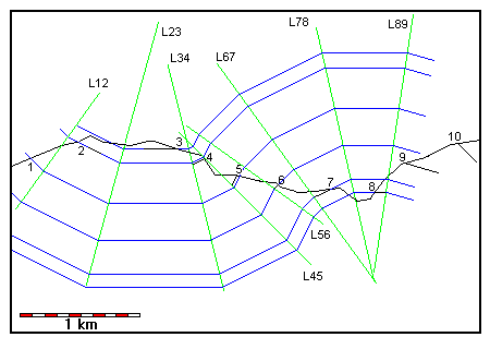 |
L89 constructed. Datum point 9 lies between two already constructed lines and is not likely to tell us anything we don't already know. For now we omit drawing a line through it. |
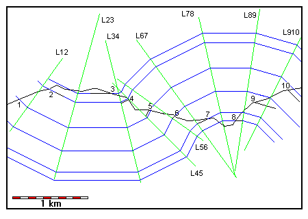 |
L910 completed. Since point 10 falls close to an already drawn line, there is no real need to construct another line for it, either. |
Tying the Diagram to Reality
It is virtually certain when you draw a cross section using strictly geometric methods that the contacts will not match exactly with their predicted positions. There are many reasons why not:
- The units will not be uniform in thickness
- There are small construction errors
- Dips are not uniform from place to place
- Dip measurements have small errors
- Folds do not have ideal geometrical shapes.
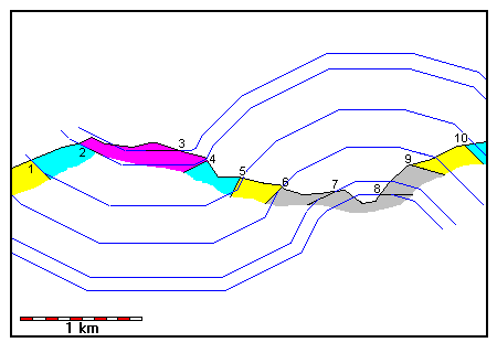 |
Here we have indicated the stratigraphy. It is virtually certain when you draw a cross section using strictly geometric methods that the contacts will not match exactly with their predicted positions.
What we need to do now is redraw the folds so the cross-section matches both the dips and the stratigraphy. |
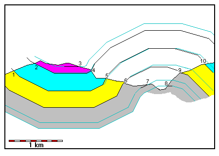 |
Here the cross section lines are subdued.
Most of the time you can modify the fold shapes by hand to match the stratigraphy without too much trouble. Modified contacts are in black. |
Do not get distracted by your dip symbols or stratigraphic colors. The only requirement is that the stratigraphy and dips match on the surface. Be prepared to modify the colors and depart from the dips below the surface if it's called for. Compare the two diagrams above to see that this was actually done.
Return to Course Syllabus
Return to Techniques Manual Index
Return to Professor Dutch's Home Page
Created 18 October 2000, Last Update 20 October 2000